
The Preesall Salt Industry - Part 4-Engineering Techniques, 1875-1926.
by Rosemary Hogarth and Geoffrey R Binns
PUMPS, AIR COMPRESSORS AND GENERATOR SETS AT PREESALL WORKS
FRESH WATER WELLS
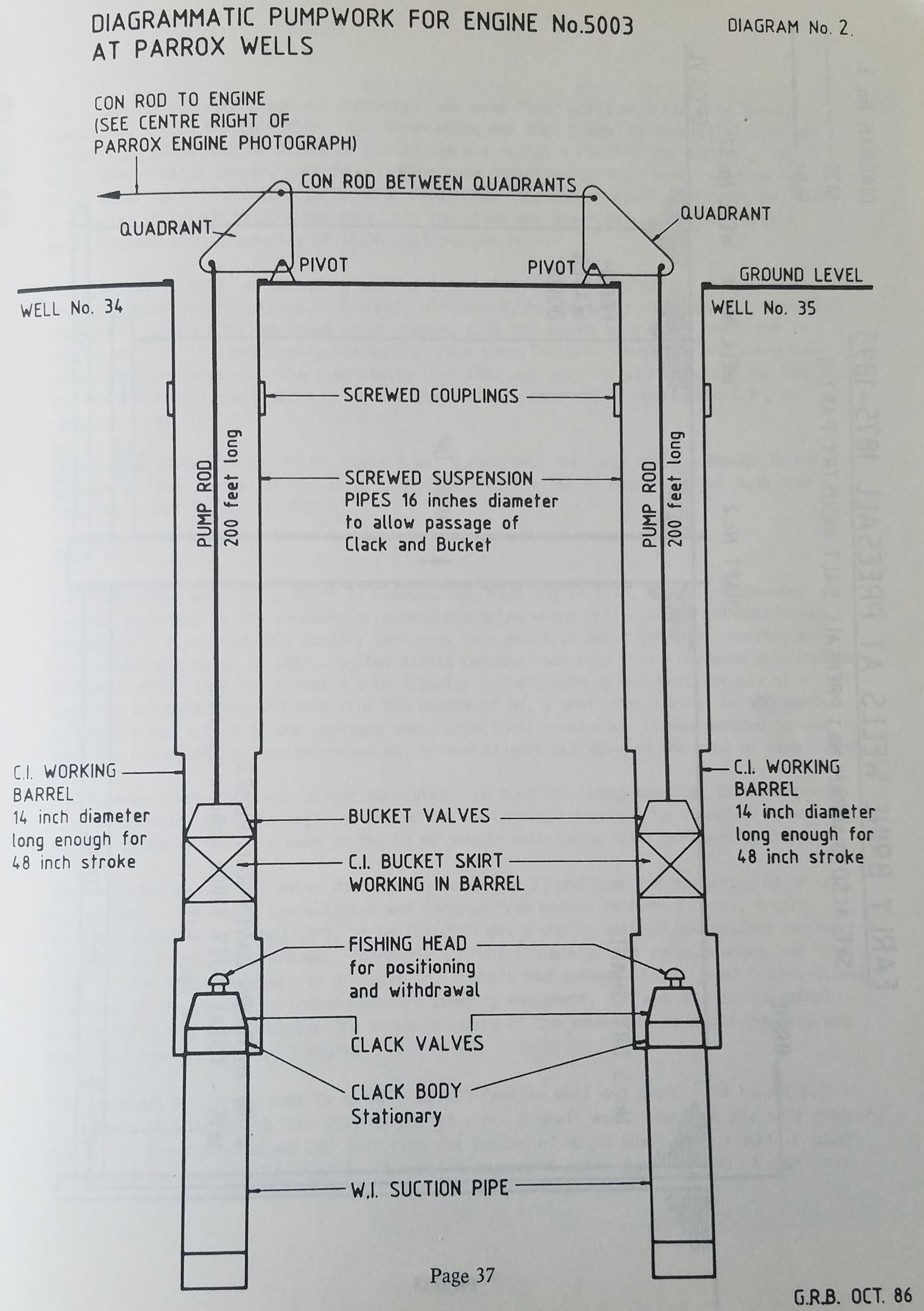
Between 1892 and 1894, Charles Chapman, Well Driller of Salford, sank two wells, reference numbers 34 & 35 and known locally as Parrox Wells, for United Alkali Co., to supply fresh water to their Ammonia Soda works at Burn Naze (1). These wells were drilled in sandstone east of the fault about 400 feet deep. The first 200 feet was 24 inches diameter and the remainder to the bottom was 18 inches diameter. It is probable that the Diamond Tool method of drilling was used.
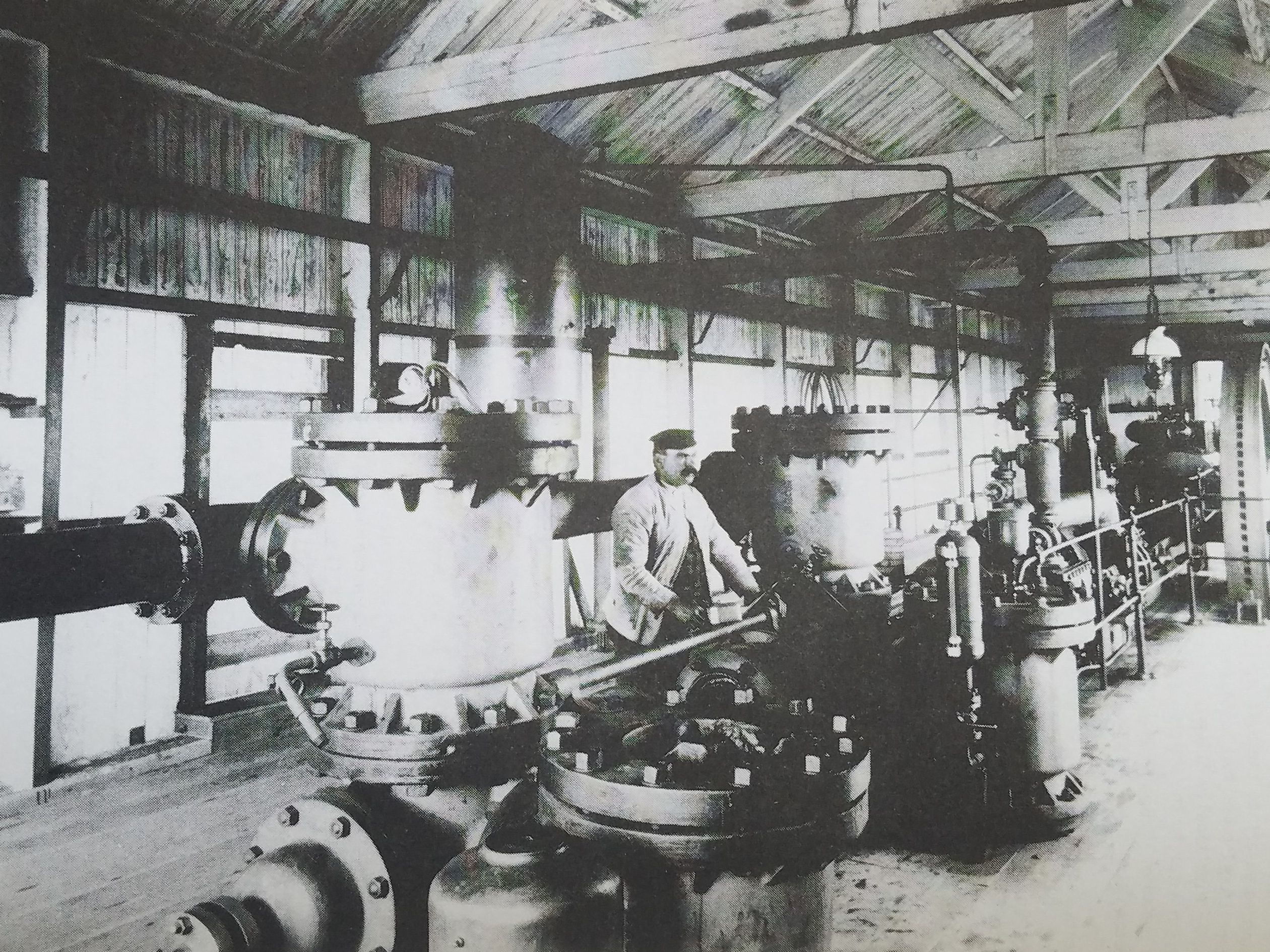
An order was placed with Hathorn Davey of Sun Foundry, Leeds (their order and engine number 5003, dated July 1892 - Extract I), for a pumping installation to raise 42,000 gallons of water per hour 200 feet from these wells and deliver a further 30 ft into a storage tank. The completed system costing £2,700 including two Cornish boilers was delivered via Pilling Station on 4 November 1893 and commenced work in 1894. (Photograph 1 and Diagram 2.)
In 1896, the water quality deteriorated probably due to draw down of the well caused by overpumping the aquafer. A geologist was consulted and he recommended further wells be sunk at a site one and a quarter miles from Parrox which became known as Klondyke. A scheme was prepared incorporating four wells and Hathorn Davey pumping equipment. This proposed scheme was abandoned.
An earlier water well, reference No. 17 (2), near to the Parrox Wells Nos. 34 and 35 was rebored in the period 1894 to 1896 when experiments were being carried out with an air lift pumping system for water.
It is recorded that a "bull pumping engine" was fitted to well No. 17 in 1894, but this was probably an early effort to increase the yield of this well. This well was deepened in 1901 to 502 feet "to give sufficient depth for the air pipe".
An air lift pump was simply a long air pipe attached to the bottom of the pipe lining the well. Compressed air was bubbled into the bottom of the air pipe reducing the density of water in the well pipe. This difference in density created the circulating pressure needed to lift the aerated waters to the surface. There were no moving parts but it was expensive in energy terms. The main advantage was that the steam engine and air compressor could be located near the boiler house and the energy in the form of compressed air could be piped over long distances. With mechanical pumping the boilers and pumping engines had to be at the well head.
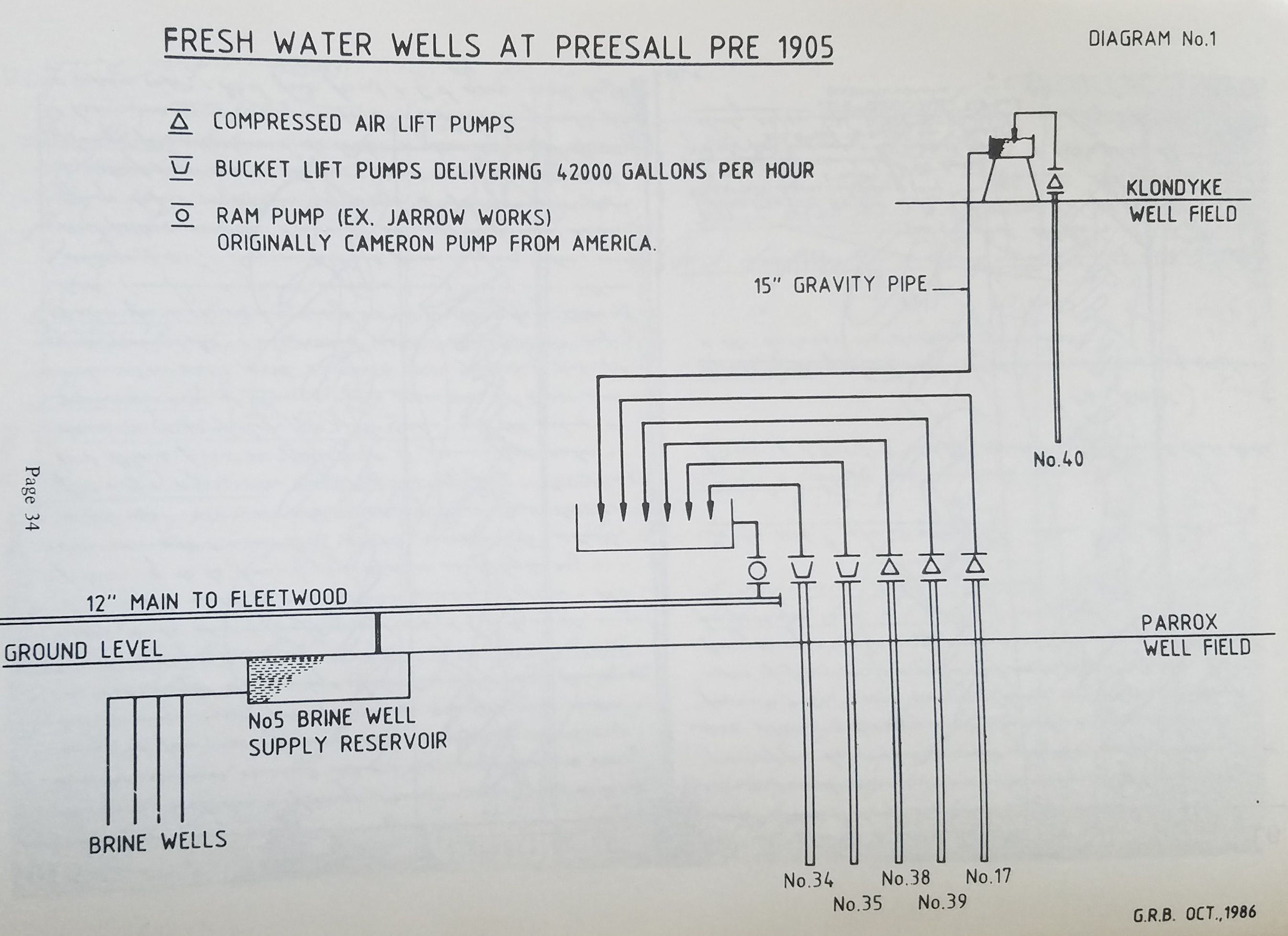
A small Ingersoll Sergeant air compressor was fixed alongside the tail rod rams of the Hathorn Davey engine to work this well. Water was raised out of well No. 17 and delivered into an open tank at ground level. A Cameron Pump then fed the water from this tank into the 12" delivery main. Ingersoll, Sergeant and Cameron were American companies and the equipment described would have come from New York.
Wells numbered 38 and 39 were sunk in 1902 and 1903 respectively and fitted with air lift pumps in the Parrox Well Field, at the same time as a compound condensing engine driven Ingersoll Sergeant air compressor was installed with an output of '1700 feet' (3).
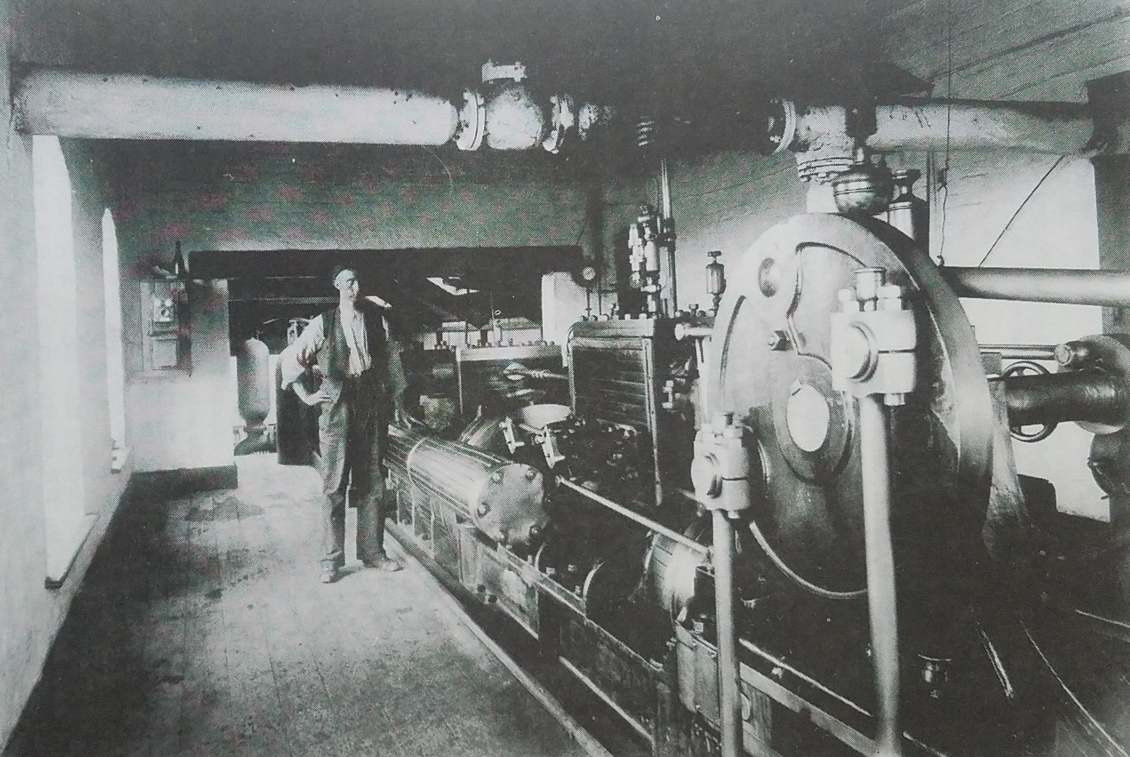
Photograph No 1. Bill Redman in Parrox Pump House
In 1903 well No. 40 was put down in Klondyke worked by compressed air fed from Parrox via a 6 inch diameter pipe. The water from well No. 40 at Klondyke ran down a 15 inch water main by gravity the one and a quarter miles to the Parrox storage tank. A large ram pump, originally from United Alkali Company Works at Jarrow, was re-erected at Parrox Well Field replacing the Cameron to pump the water into the 12 inch main which supplied the main works at Fleetwood over the River Wyre and the No. 5 brine well supply reservoir. (See Diagrams No. 1 and No. 2.)
Up to 1905, there was at Parrox Well Field a steam boiler plant feeding the Hathorn Davey bucket/plunger pumps, the ex-Jarrow ram pump and an Ingersoll Sergeant air compressor. This air compressor was connected into a 6 inch ring main which fed each air-operated well with a 2 inch branch supply.
In 1905 the water and air systems were electrified and at the same time modified. The steam boiler plant and the Hathorn Davey pump were closed down but held on standby in case of failure of the electrical supply.
The electricity was generated at the salt mine, about one and a half miles from the fresh water wells, by a Belliss and Morcom steam engine driving a British Thompson Houston 60 KW, 550 volt, 3-phase alternator. Maker's engine number 2721 built 6 October 1905. The engine steam pressure was 145 psi non-condensing against 3 lbs back pressure running at 500 rpm and developing 90 BHP.
A second Belliss & Morcom engine No. 4834 with a Westinghouse alternator was installed on 5 February 1912 to supply the increased load in parallel to engine No. 2721. The alternator was rated at 100 Kw and the steam engine developed 150 BHP when running at 428 rpm when supplied with steam at 130 psi and 3 psi exhaust back pressure.
Belliss & Morcom have records of servicing these engines up to 1925, after that they would be serviced by ICI. However, No. 2721 was serviced by Belliss & Morcom in 1946 at Carlton Colliery, Grimethorpe and No. 4834 at Black Dyke Mills, Queensbury in 1942 and W. H. Eastwood Ltd., Worsted Spinners, Elland, 1951-3.
The Ingersoll Sergeant large air compressor was sent from Parrox Well Field to supply compressed air to the Salt Mine. The fresh water was then pumped by electrically driven centrifugal pumps made by Allens of Birmingham and Mather & Platt of Manchester. Two other electrically driven, centrifugal pumps were installed at No. 5 pump house to supply fresh water to the Ammonia Soda Works at Fleetwood. One was an Allen of Birmingham, with a capacity of 40,000 gallons per hour, and the other was described as a "Rees Roturbo Motor Driven" with a capacity of 18,000 gallons per hour.
Years later, in 1924, an agreement was drawn up between the United Alkali Company and Preesall Urban District Council to supply electricity to the whole of Preesall. Preesall UDC agreed to pay £350 per annum basic charge, plus the amount of current used, for 15 years, and erected transforming stations at Park Lane, Cartgate, the Mount and Sandy Lane (now a slipper factory). The electricity cost 10d. per unit for lighting, 2d. for heating, 3d. for industrial power and 4d. for poultry cabins - each use of course requiring a separate meter.
On Saturday 19 December 1925 the current was turned on. One very obvious change in the village was the removal of the sails of Preesall Mill after it changed on 18 June 1926 from wind power to electricity.
BRINE WELLS
The first brine well No. 2 shaft in Preesall was hand dug in 1875, 8 feet in diameter and 400 feet deep to the rocksalt level and the brine which collected in the bottom was pumped out. Fleetwood Salt Company took over this shaft in about 1883 and inserted a 'bull pumping engine' in 1885. United Alkali Company took over from Fleetwood Salt Company in 1890, and in 1891 two 5 feet 5 inch diameter tunnels were driven horizontally at a depth of approximately 610 feet from the bottom of No. 2 shaft for a total of 500 yards to explore the extent of the rocksalt bed. Upon their completion it was decided to use them for brine making, and boreholes No. 36 and 37 were put down at the ends of each tunnel.
The foreman at the time was Oliver Bannister. He took his young son Jim, later to become foreman himself, into the empty cavity of No. 36 borehold through the tunnel from No. 2 shaft; probably the only case in the UK of people entering a solution-mined cavity.
The intention was to put water down boreholes 36 and 37 and pump the resulting brine up A pumping installation was ordered from Messrs Hathorn & Davey, Engine No. 5059 dated 10 February 1893, to be fixed in No. 2 shaft, duty 27,000 gallons per hour 650 ft high using 92 Horsepower. (Appendix 1) Unfortunately, the repairs which had from time to time been necessary to preserve No. 2 shaft had reduced its original 8 feet diameter and made it too narrow to accommodate the pumping equipment. It was decided to select a site for a new shaft outside the known boundary of the rock salt to avoid the problems which had occurred in No. 2 shaft.
The new shaft No. 5 was sunk to a depth of 600 feet in marl and a 400 yard tunnel driven to connect it with No. 2 (see Diagram No. 3). No. 5 shaft was to be kept dry so a stopping was put in the tunnel about 140 feet from the bottom of No. 5 shaft with a suction pipe connecting the pumps to the brine. A small independent water pump kept No. 5 shaft dry.
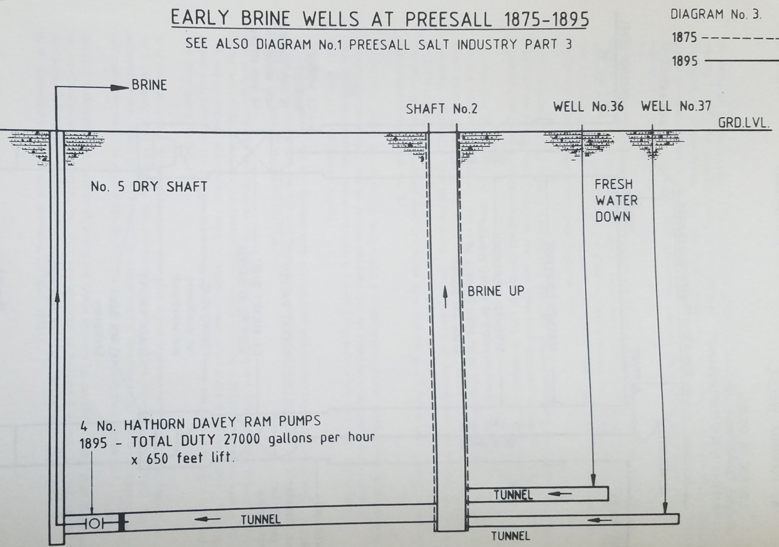
A change was made in the Hathorn Davey order from bucket/plunger pumps to ram pumps. A new pump house was built adjacent to No. 5 brine well and the machinery was delivered on 31 July 1895. (Photograph 2.) F. J. Thompson in his notes states, "Complete design of pumps and shaft is shown on drawing No. 261 in the office". (This drawing No. 261 is thought to be a Hathorn Davey drawing.) This system was not used after 1911 but left in a state of equilibrium; saturated brine at the No. 2 side of the stopping and natural water at the No. 5 side.
Photograph No 2. Pump Hose No. 5
Suction and Delivery valves for Engine No 5059 (not in picture)
In 1920 this equilibrium ceased. A leakage caused the brine and water to mingle, dissolving more salt, and brine began running Into the mine. In 1924 the Directors of the united Alkali Company allocated £3,000 to the infilling of No. 5 shaft and tunnel. The job was completed in January 1926. It had not been possible to work more than 3 men in the tunnel and shaft. They had successfully stopped the brine run, isolated the water at its natural level in No. 5 shaft, and filled in the tunnel and No. 5 shaft with clay, rubble and cement. F. J. Thompson wrote, "It is largely due to the superior intelligence and devoted work of these men that the whole job was so successfully completed without any accident or loss of material".
No. 36 borehole remained empty until about 1960 when ICI thought it prudent to fill it with saturated brine so its dimensions could be measured by echo-sounder. It turned out to be of a very satisfactory and stable form and could have continued to stand empty without trouble.
DRILLING AND OPERATING THE BRINE WELLS
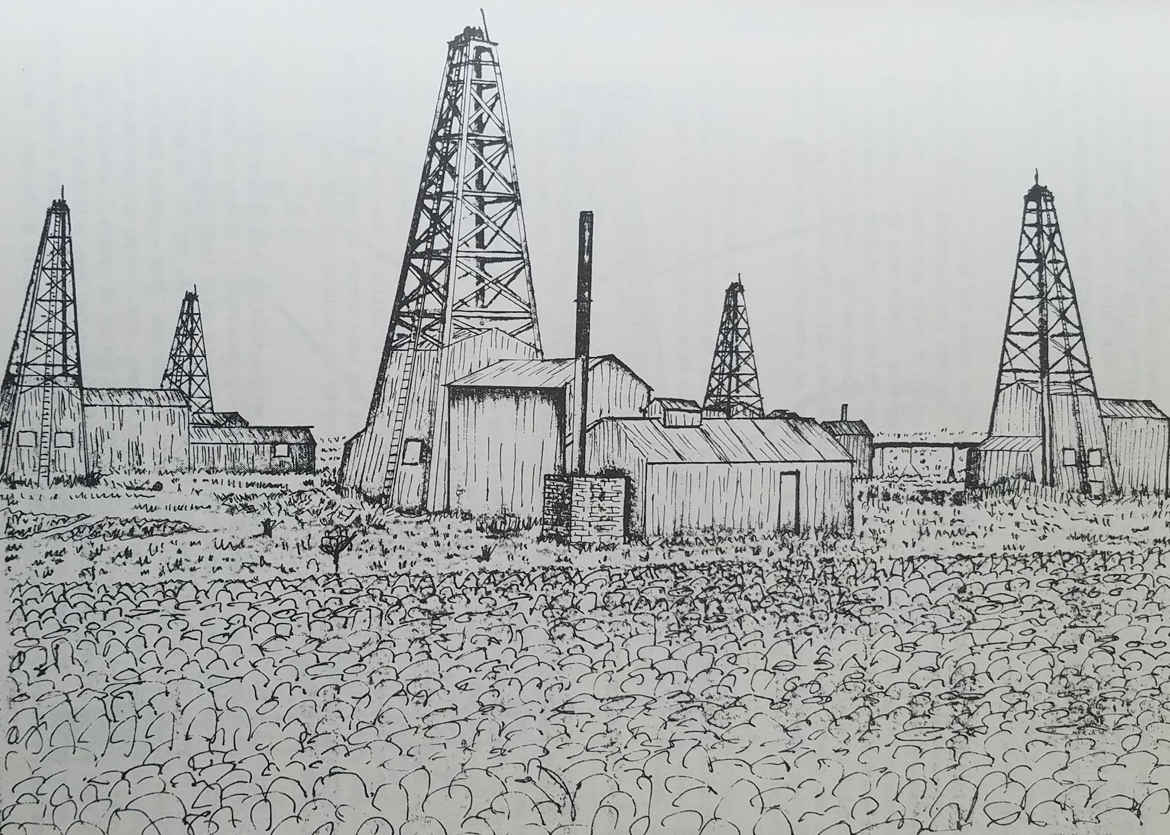
Illustration 1 shows five drilling "rigs" at Almonds or Oldmans. The rigs in their earliest operating mode served three distinct purposes. The first was drilling the well. The second was putting in and taking out of the lining tubes. At Preesall the lining tubes were put in at the same time as the hole was being drilled but the derrick was left in position for withdrawing the tubes when the well was exhausted. The third was operating the well using the drilling gear for pumping brine.
The method used was called the cable tool system. In the 1890s this American system, although new to England, was old to America. The system of drilling required considerable practice but when acquired it was rapid, economical and very simple in operation, costing in 1891 approximately 10 shillings a foot according to the geologist of the day, Charles E. De Rance.
It consisted of a string of tools (see Diagram 4) merely drilling through the rock, which reduced it to a coarse powder suspended in water, then removing this slurry by means of a sand pump; the two operations being repeated in sequence until the required depth was achieved. The wells at Preesall, Nos. 30, 31, 32, 33, 43, 44, 48, 50, 53, 54 and 55. were drilled by a Swedish American from California - some say Texas - called Charlie Olston who worked behind closed doors with only one local helper, Bill Anyon, and insisted that he was paid in American dollars every pay day. He was buried at Preesall cemetery in May 1920 aged 64. A previous American named Charlie Frazer had been drilling on this site as early as 1889. They were called "the two Charlies". Charlie Frazer always carried a gun and used very colourful language. Bill Anyon went on to drill at Penketh. He was a very conscientious man and committed suicide by jumping into the St. Helen's canal when he thought, wrongly, that he had drilled a well out of alignment!
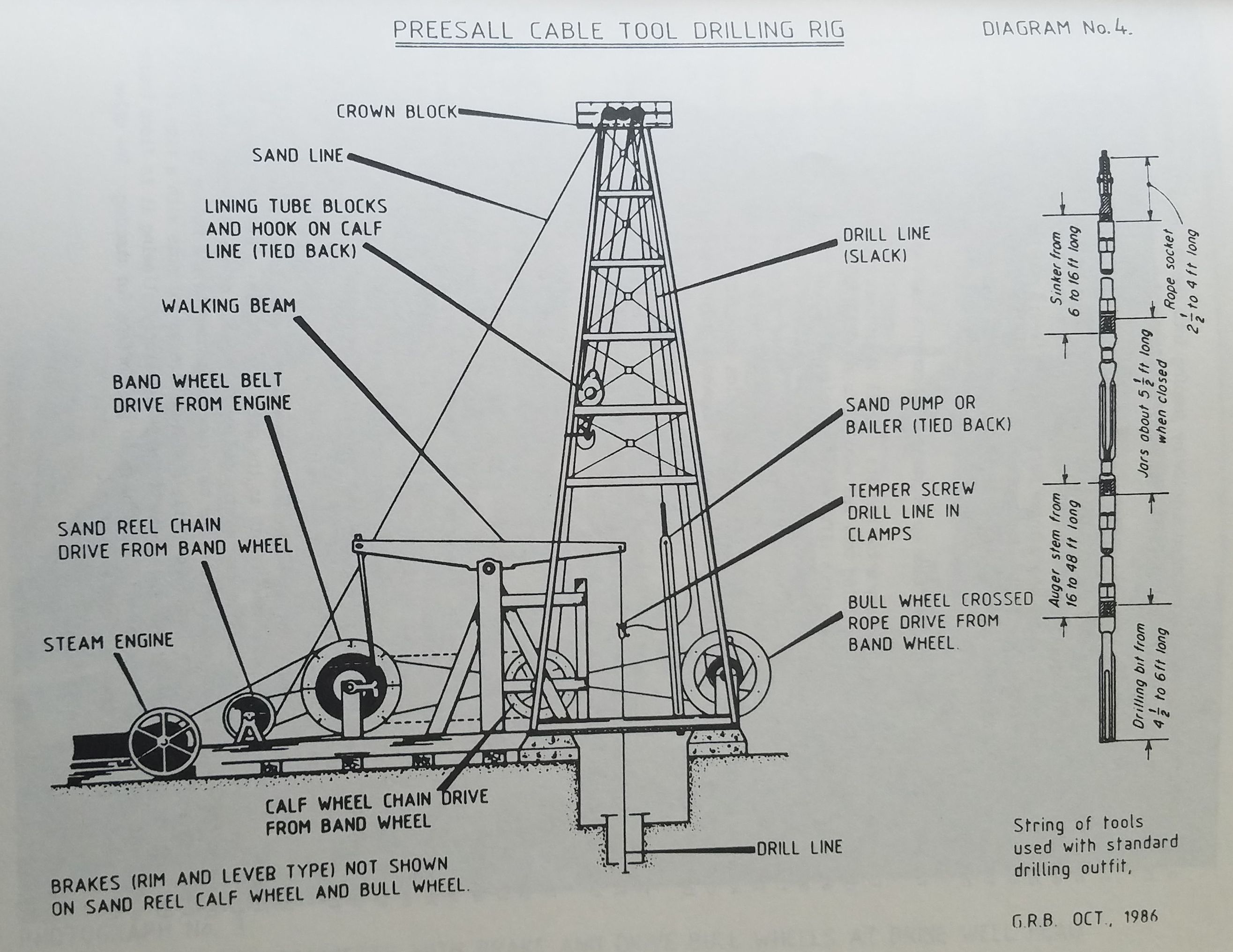
The rig was constructed of spruce with pitch pine foundation blocks and consisted chiefly of a derrick, bull wheel, calf wheel, sand pump reel, band wheel, walking bean, engine The rig was constructed of spruce with pitch pine foundation blocks and consisted chiefly and engine house. (Diagram 4.) The derrick was about 76 ft high, 20 ft square at the tools, one for the sand pump and one for the lining tube lifting blocks. Both the drilling base and 3 ft square at the top where three pulleys were fixed; one for the drilling tools and the lining tubes were each about 60 ft long and were supported inside the 76 ft high derrick.
The 60 ft long drilling tool was made up of various components each with a separate function.
The composite tool weighed nearly a ton and its overall length was designed to keep the drilled hole straight. The cutting tool was similar to a garden spade with the handle a little off centre. The continuous lifting and dropping action of the rope caused the spade to swivel round cutting a hole bigger than the blade itself. To keep the drill turning, a man walked round with a twitchel - an ash pole lashed to the drilling rope. This system allowed the lining tubes to be put in place and still allow the drilling blade, known as an eccentric spudding, to be withdrawn up inside the lining tube. Another important component of the drilling tool was the jars which allowed a sharp snatching action to be applied if the drill got stuck.
The cable, a 3 inch diameter manilla rope at least as long as the well depth plus allowances for passing up and down the derrick, was fixed at its upper end on the drum between the two bull wheels and its lower end to the drilling tool.
The walking beam provided the up and down motion to the drill by clipping on to the long cable at the appropriate place with an ingenious quick release grip or clamp called a temper screw. The walking beam was reciprocated at the opposite end from the cable by a crank on the band wheel shaft which was turned by a belt from the engine. The length and frequency of each stroke was readily adjusted at the crank and the engine speed control When the bit had progressed about 4-6 ft into the rock it would be time to bale out the crushed rock and water from the hole. The temper screw would be released and the bull wheel would be turned by the belt over its rim being driven by the band wheel. drill was out of the hole the flat iron brake was applied to the other bull wheel and the drill was pulled aside and held.
The sand pump was released from its stowed position and allowed to enter the drilled hole. It was lowered on a cable, the same length as the drill cable whose other end was attached to the sand reel. This cable also went over a pulley at the top of the derrick. The brake on the sand reel was released and the sand pump descended to the bottom of the hole. The sand pump consisted of a long tube nearly the same size as the hole with a flap at the bottom. The flap opened when going down through the slurry allowing it to flood inside and closed when rising, thus carrying the slurry to the surface for dumping. The drive for the sand reel was taken off the band wheel.
The next length of lining tube was already hanging on its lifting blocks inside the derrick having previously been hoisted there by a drive from the calf wheel via a rope over the third pulley at the top of the derrick. When the hole was deep enough the new length of liner was screwed to that already projecting at the wellhead and the whole was lowered into place.
The drill, after inspection for sharpness, was either changed or put back down the hole against the band brake on the bull wheel. On reaching the bottom the temper screw was clamped to the cable and the nodding of the walking beam recommenced.
Mr Harold Daniels tells us -
"To start with, 14 inch diameter tubes were banged down the drilled hole through the boulder clay by a square log of timber, round at the bottom, lifted and dropped by the walking beam. Once marl was reached by the drilling, 10 inch tubes were lowered down through the 14 inch ones to continue down the well. When the drilling reached salt 8 inch diamete tubes were used. The first 8 inch diameter tube had a bell mouth. When the well was the required depth, the 8 inch tubes were continued up to the surface. A cement "grummit" was poured between the 8 inch tubes and the 10 and 14 inch ones which were lifted out before the cement set, leaving an 8 inch well to the full depth of 400 to 600 feet. After the cement around the 8 inch liner tube was set a 3 inch liner tube was inserted down the middle right through the bell mouth of the 8 inch tube on top of a bucket pump. The spindle of the bucket pump being lifted and lowered by the walking beam".
At a later stage, the water was pumped down the well from the surface forcing the brine up the central brine delivery tube. The derrick and bull wheels were retained in position after the steam engine and walking beams were dismantled and removed. They were used for withdrawing the tubes when the well was exhausted by utilising a crow bar and the pegs projecting from the side of the bull wheels. (Photograph - 3.)
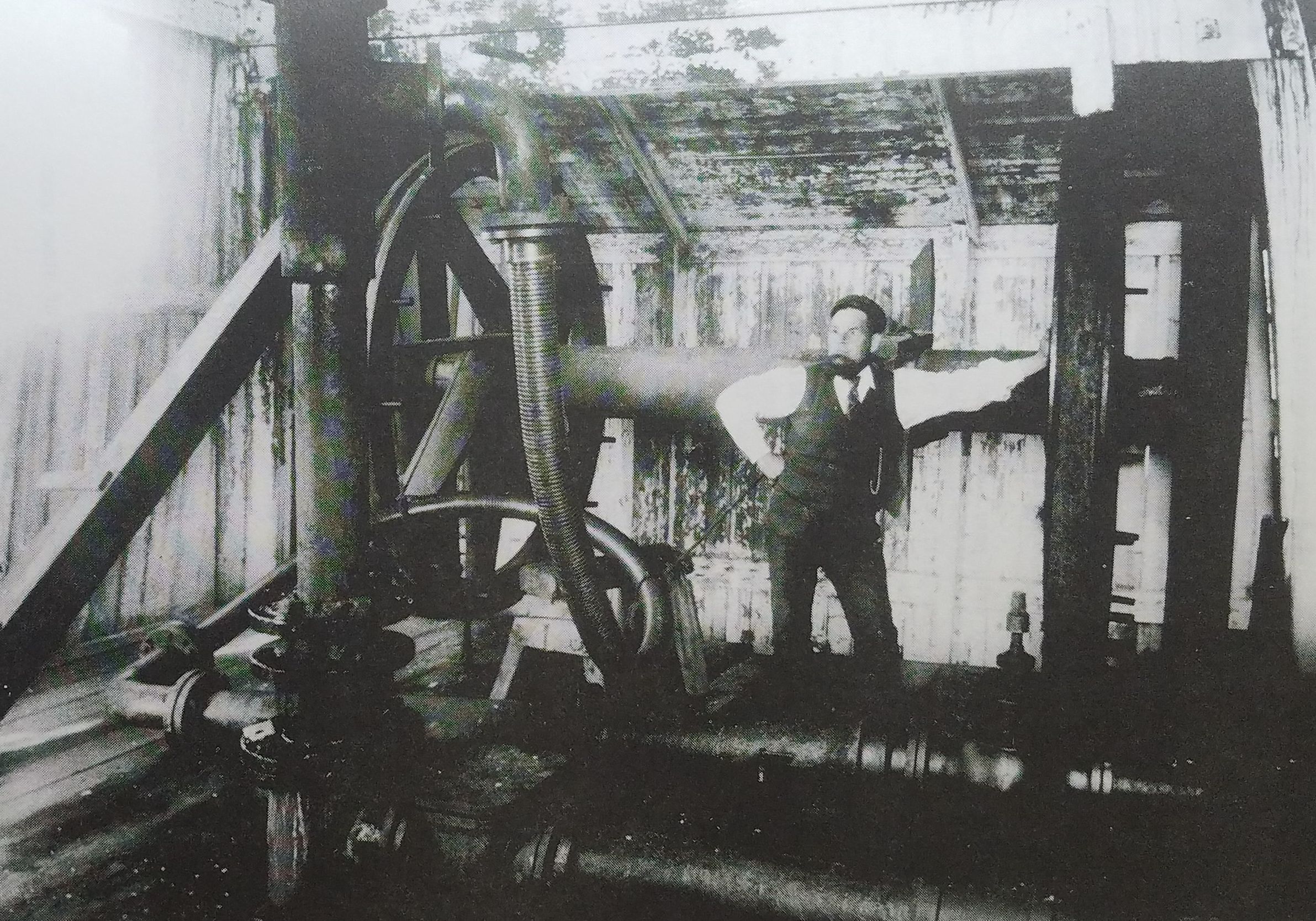
Photograph No 3. Oliver Bannisterwith brake and drive bull whees at Brine Well Head
Occasionally, when the 3 inch brine tubes became blocked with sediment, the steam engine was brought back and the 3 inch tubes lifted to dislodge the sediment.
The wells of today stand outside exposed to the elements as the well can be drilled by a mobile rig. In Autumn 1985, wells Nos. 124 and 125 were drilled by such a rig within two months.
Appendix 1
The performance had to be guaranteed and money was retained until satisfactory proving tests had been completed. The order states -
"The duty to be 90 millions on 1008 lb of feed water".
This means 90,000,000 ft lb of work per hour for every 1008 lb of steam used.
Now 33000 ft lb of work per minute equals 1 horsepower, so if we divide 90,000,000 by AP of each pump. Dividing this figure into 1008 lb of steam we get a consumption of 33000 and then by 60 we arrive at a figure of 45.45 BHP or a figure approximating to the 22.2 lb of steam per brake horsepower.
This figure compares favourably with that set by the United Alkali Company on Bellis & built 6 October 1905. (A modern triple expansion pumping engine of the 1920s or 1930s Morcom of 28 lb of steam per brake horsepower for the alternator steam engine No. 2721 using superheated steam would have attained a consumption of about 10 lb of steam per brake horsepower.)
References
1. Rosemary Hogarth, The Preesall Salt Industry Part 2, 1892-1911 in The Over-Wyre Historical Journal Vol. II.
2. R Hogarth and W Heapy, The Preesall Salt Industry Part 1, 1872-1891 in The Over-Wyre Historical Journal Vol. I.
3. FJ Thompson "An Account of the Salt Deposits at Preesall - Fleetwood and their development" unpublished ICI 1927.
4. Rosemary Hogarth, The Preesall Salt Industry Part 3, 1912-1923 in The Over-Wyre Historical Journal, Vol. III.
Acknowledgements
Mr Harold Daniels Preesall
Mr J Hoyle Belliss & Morcom Ltd
ICI Ltd
Mrs Lindley Leeds City Archives
Dr Peter McFarlane ICI Ltd
Mr J Stevenson Ingersoll Rand Ltd
Judith Swarbrick and Diana Winterbotham Lancashire County Library, Preston
Mr G Twigg Sandbach, Cheshire
Mr A H Wilkinson Sulzer Bros (UK) Ltd, Leeds